Running a link budget against a dedicated antenna you own is straightforward: you know the system noise temperature, the LNA gain, the feed losses, and the pointing error budget. When you move to a managed ground station network, three parameters shift enough to warrant a fresh calculation for every new site configuration you plan to use. This piece walks through those shifts and how to account for them rigorously.
The Baseline Equation and Where GSaaS Changes It
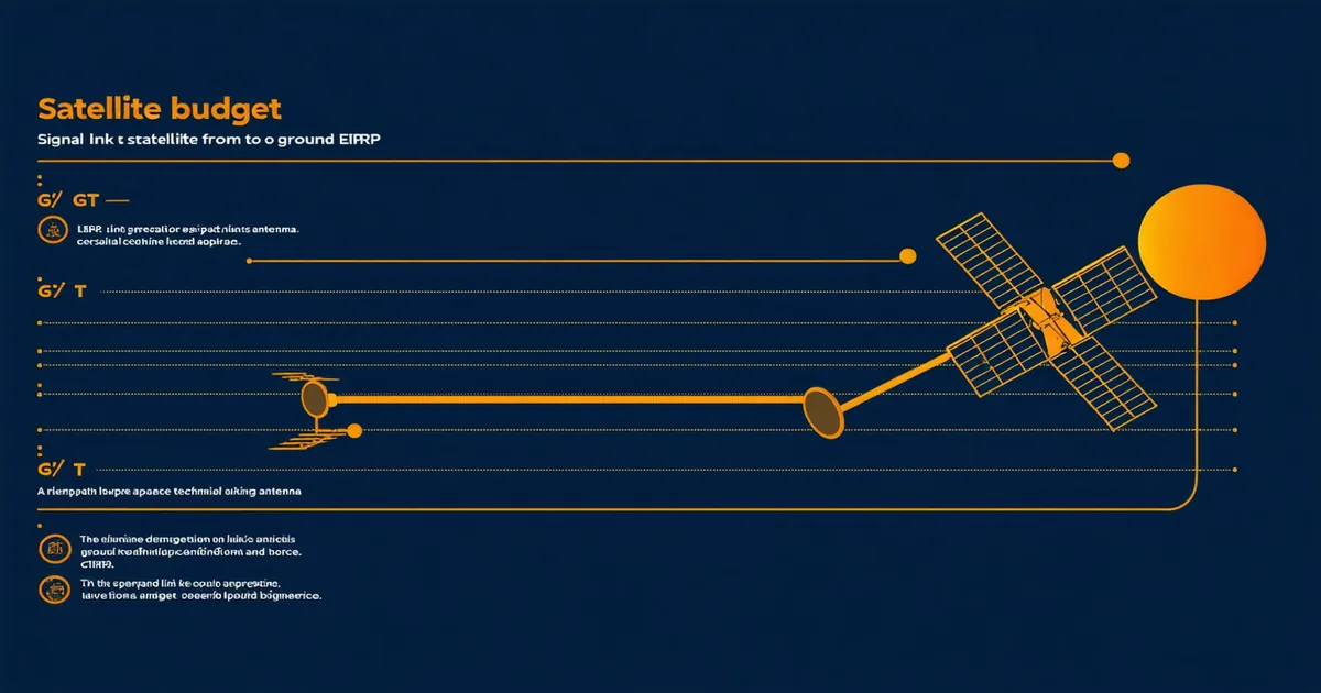
The received carrier-to-noise density ratio is built from a small number of terms:
C/N₀ = EIRP − FSPL − Latm − Lother + G/T − k
where EIRP is the spacecraft transmitter's effective isotropic radiated power in dBW, FSPL is free-space path loss, Latm is atmospheric and rain attenuation, Lother covers polarization mismatch and pointing error losses, G/T is the ground station's figure of merit in dB/K, and k is Boltzmann's constant (−228.6 dBW/Hz/K).
In a dedicated-antenna scenario you control every term on the right side except FSPL and Latm. In a GSaaS scenario, the G/T value and the Lother contributions become parameters you inherit from the network provider's station spec sheet — and those specs need scrutiny.
G/T Variability Across Aperture Classes
Orbitvein's network includes apertures from 3.7 m to 9 m. The G/T spread across those apertures at X-band is roughly 20 dB/K for a 3.7 m dish with a 60–75 K system noise temperature, rising to approximately 28–29 dB/K for a 9 m aperture with a cryogenic LNA at 35–50 K system temperature. At S-band, the figures drop by roughly 10–12 dB due to the lower gain of the antenna at that wavelength.
What matters operationally is that when you book a contact window, you need to know which aperture class is being assigned before you finalize your link margin calculation — not after. A contact on a 3.7 m station with a warm-LNA front end may produce a C/N₀ 7–8 dB lower than the same contact on the 9 m dish. For a spacecraft transmitting at 40 dBW EIRP on X-band at 500 km altitude, that difference can push you from a comfortable 3 dB margin above your DVB-S2X threshold down to a margin that requires dropping from 8PSK to QPSK, halving your effective data rate.
A Plausible Scenario: 400 km LEO Earth Observation Mission
Consider a small LEO Earth observation satellite, 6U form factor, operating at 8.025 GHz X-band, downlink data rate target of 150 Mbps during a 7-minute contact window. The spacecraft transmitter is rated at 2 W (33 dBm), antenna gain of approximately 6 dBi, giving EIRP of roughly 39 dBW. At 400 km altitude and 5° minimum elevation, FSPL runs approximately 155 dB. Atmospheric loss at low elevation adds 0.5–1.5 dB depending on weather. Polarization mismatch between spacecraft and ground (assuming RHCP spacecraft antenna and linear ground feed) contributes 0–3 dB depending on orbit orientation.
Against a 3.7 m aperture (G/T ≈ 20 dB/K):
C/N₀ ≈ 39 − 155 − 1.0 − 1.5 + 20 + 228.6 ≈ 130 dB·Hz
For 150 Mbps using DVB-S2X with QPSK 1/2 (Eb/N₀ threshold ≈ 1.0 dB), required C/N₀ ≈ 10 log₁₀(150×10⁶) + 1.0 = 82.8 dBHz. That leaves a margin of approximately 47 dB — far more than needed, but the satellite is transmitting at low EIRP. Increase to 10 W transmitter (40 dBW EIRP), move to 16APSK 3/4 mode (Eb/N₀ threshold ≈ 8.7 dB), and your required C/N₀ rises to about 90 dBHz. Your margin against a 3.7 m station narrows to roughly 7–8 dB at best elevation, dropping toward 2–3 dB at 5° elevation due to additional path loss. That is a realistic constraint.
Atmospheric Loss and the Elevation Angle Problem
FSPL at 5° elevation for a 400 km circular orbit is approximately 3–4 dB higher than at 90°. Combined with the elevation-dependent atmosphere path (which follows roughly 1/sin(θ) for zenith-referenced zenith attenuation), low-elevation contacts have two stacking loss penalties. For X-band, zenith atmospheric loss is typically 0.1–0.3 dB in clear air; at 5° elevation that scales to 1.0–3.5 dB. At Ka-band (26.5 GHz), zenith clear-air loss is already 0.4–0.7 dB, reaching 4–8 dB at low elevation in clear conditions and well over 15 dB in moderate rain.
The practical implication for GSaaS link budget planning: we are not saying low-elevation contacts are inherently unusable — they are valid for low-rate TT&C and command uplinks where margin requirements are modest. But scheduling bulk X-band or Ka-band data downlinks at elevation angles below 10° introduces margin uncertainty that should be modeled explicitly. Orbitvein's pass prediction output includes estimated contact duration at ≥10° and ≥20° elevation masks separately, which allows operators to budget data volume against usable contact time rather than raw AOS-to-LOS duration.
Polarization Mismatch and the Circular/Linear Decision
Ground station feed polarization is a parameter that operators frequently overlook when choosing between providers. Most small spacecraft use RHCP patch or turnstile antennas for omnidirectional coverage during early mission phase; high-gain downlink antennas may be linearly polarized. A linear-polarized spacecraft antenna transmitting to a circular-polarized ground feed introduces a nominal 3 dB polarization loss regardless of orientation. A circular-to-linear configuration introduces 0–3 dB loss depending on the rotation angle of the spacecraft relative to the ground station boresight.
When using shared infrastructure, confirm feed polarization options before committing to a link budget margin. A provider that offers switchable RHCP/LHCP feeds gives you flexibility; a provider with linear-only feeds on their smaller apertures will force you to budget 3 dB of polarization mismatch for any circular spacecraft antenna configuration.
Eb/N₀ vs. Es/N₀ and DVB-S2X Threshold Planning
DVB-S2X modulation and coding thresholds are specified in terms of Es/N₀ (energy per symbol per noise power density), not Eb/N₀ (energy per bit). The conversion is Es/N₀ = Eb/N₀ + 10 log₁₀(log₂(M)), where M is the constellation order. For QPSK (M=4), Es/N₀ = Eb/N₀ + 3 dB. For 16APSK (M=16), Es/N₀ = Eb/N₀ + 6 dB. For 32APSK (M=32), Es/N₀ = Eb/N₀ + 7.5 dB.
When planning a DVB-S2X link, specify your demodulator's required Es/N₀ threshold for the target modcod, add your required implementation margin (typically 1–1.5 dB for a modern demod), and work backward from C/N₀ to check whether your link closes at the worst-case pass geometry (minimum elevation, hot LNA, heavy atmosphere). If the link doesn't close on the 3.7 m aperture, determine whether the 5.4 m or 7.3 m aperture at the same station closes it — or whether a different geographic station with lower atmospheric loading or cooler ambient temperature tips the balance.
Margin Stacking in Practice
A well-structured link budget for a GSaaS contact allocates margin across these independent uncertainty sources:
- G/T uncertainty: ±0.5 dB (station calibration tolerance)
- Pointing loss: 0.1–0.3 dB for a well-tracked contact at a precision autotrack mount
- Atmospheric scintillation (elevation-dependent): 0.2–0.5 dB at X-band above 10°
- Demodulator implementation loss: 1.0–1.5 dB
- RF hardware aging (cables, connectors, waveguide): 0.2–0.5 dB
Summing those in RSS fashion gives a total margin stack of approximately 1.5–2.0 dB. Add your modcod threshold margin target (typically 2–3 dB above theoretical) and your total required link margin above the minimum threshold should sit at 3.5–5 dB for a robust contact plan.
The one trap in shared-aperture planning is assuming the station G/T is always at its rated best-case value. Real station performance degrades gradually from feed contamination, LNA aging, and mount backlash. Good GSaaS providers publish calibrated G/T measurements on a rolling basis; that documentation matters more than the spec sheet number when you are margin-tight.